Mixing
Many tools can help to achieve proper balance and create space for the various parts of your mix. The following effects can help you craft your mix with precision and excellent sound quality.
Binaural Pan
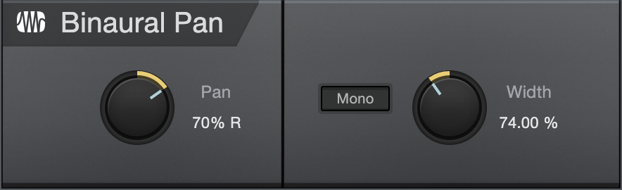
The Binaural Pan is a panning effect that employs mid/side processing to manipulate the perceived width of stereo signals, from mono to double the normal width. Use the Binaural Pan on any stereo Track to tightly control its stereo width and pan, as well as to check for mono compatibility using the Mono switch.
The following parameters are available for the Binaural Pan:
- Pan: Adjusts the balance in the left and right channels for the stereo Track. Variable from 100% L to 100% R.
- Mono: Switch to mono playback of the stereo Track.
- Width: Adjusts the stereo width of the stereo Track. Variable from 0 (mono) to 200% (double stereo width).
The Binaural Pan can only be used on stereo Tracks. If loaded onto a mono Track, the plug-in display shows “MONO CHANNEL.”
Channel Strip
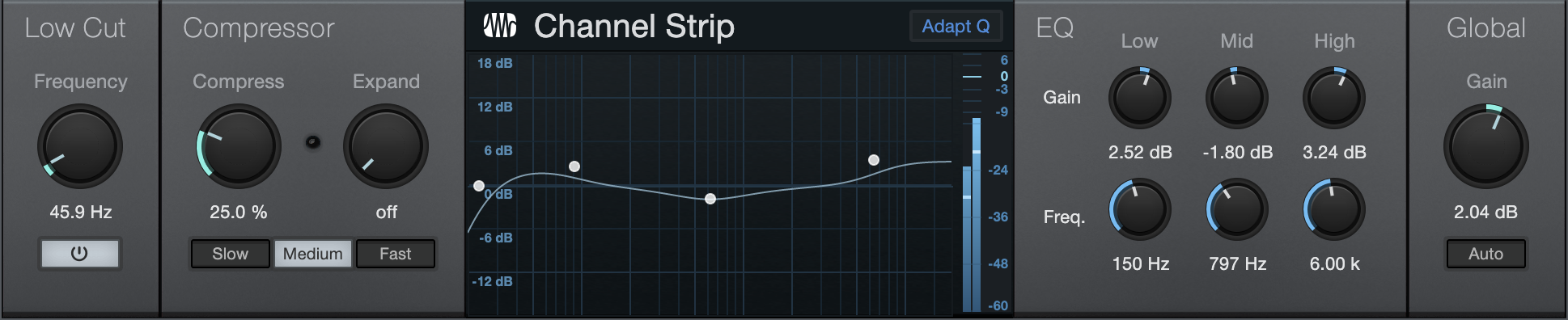
Channel Strip features three processors in one, including a low-cut filter, dynamics processor, and three-band parametric EQ. Channel Strip optionally applies automatic gain correction to the EQ so that the input-signal power matches the output signal power. Use Channel Strip on any mono or stereo Track that needs basic channel processing.
The following parameters are available for Channel Strip:
- Low Cut Active: Click on the Low Cut Active button to engage/disengage the Low Cut filter.
- Frequency: Adjusts the Low Cut Frequency to change the filter cutoff frequency. Variable from 40 Hz to 400 Hz.
- Compress: Adjusts the compression amount. Variable from Off to 100%. Simultaneously adjusts threshold (0 dB to -20 dB) and ratio (2:1 to 10:1).
- Expand: Adjusts the expansion amount. Variable from Off to 100%. Simultaneously adjusts threshold (-64 dB to -24 dB) and ratio (1.5:1 to 2.5:1).
- Active gain reduction is indicated by a red “LED"-like indicator.
- Slow, Medium, Fast: Adjusts the RMS averaging speed. Slower speeds may reduce artifacts with some audio material. The default is Medium, and Studio One Pro version 1 presets open set to Fast.
- Adapt Q: Enable to change band Q depending on the level of boost or cut applied.
- Low, Mid, High: Adjusts gain and frequency for each band of the parametric EQ. Each band has fixed Q.
- Gain: Adjusts the output gain of the Channel Strip. Variable from -12 dB to 12 dB.
- Auto: Click to engage automatic output-gain setting. This guarantees that a 0 dB input signal equals a 0 dB output signal.
Dual Pan
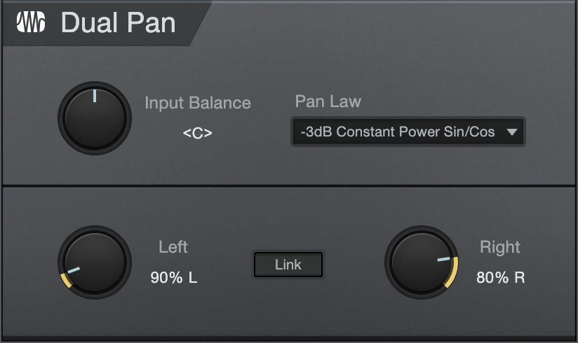
Dual Pan is a fully variable stereo panner with input balance control, selectable pan law, and independent left/right panning. The following parameters are available for Dual Pan:
- Input Balance: Adjusts the balance of the stereo input signal from full left to full right.
- Pan Law: Select a pan law, choose from -6 dB Linear, -3 dB Constant Power Sin/Cos, -3 dB Constant Power Sqrt, 0 dB Balance Sin/Cos, and 0 dB Linear.
- Pan:
- Left: Adjusts the pan of the left input signal from full left to full right.
- Right: Adjusts the pan of the right input signal from full left to full right.
- Link: Link the Left and Right panning.
Fat Channel XT
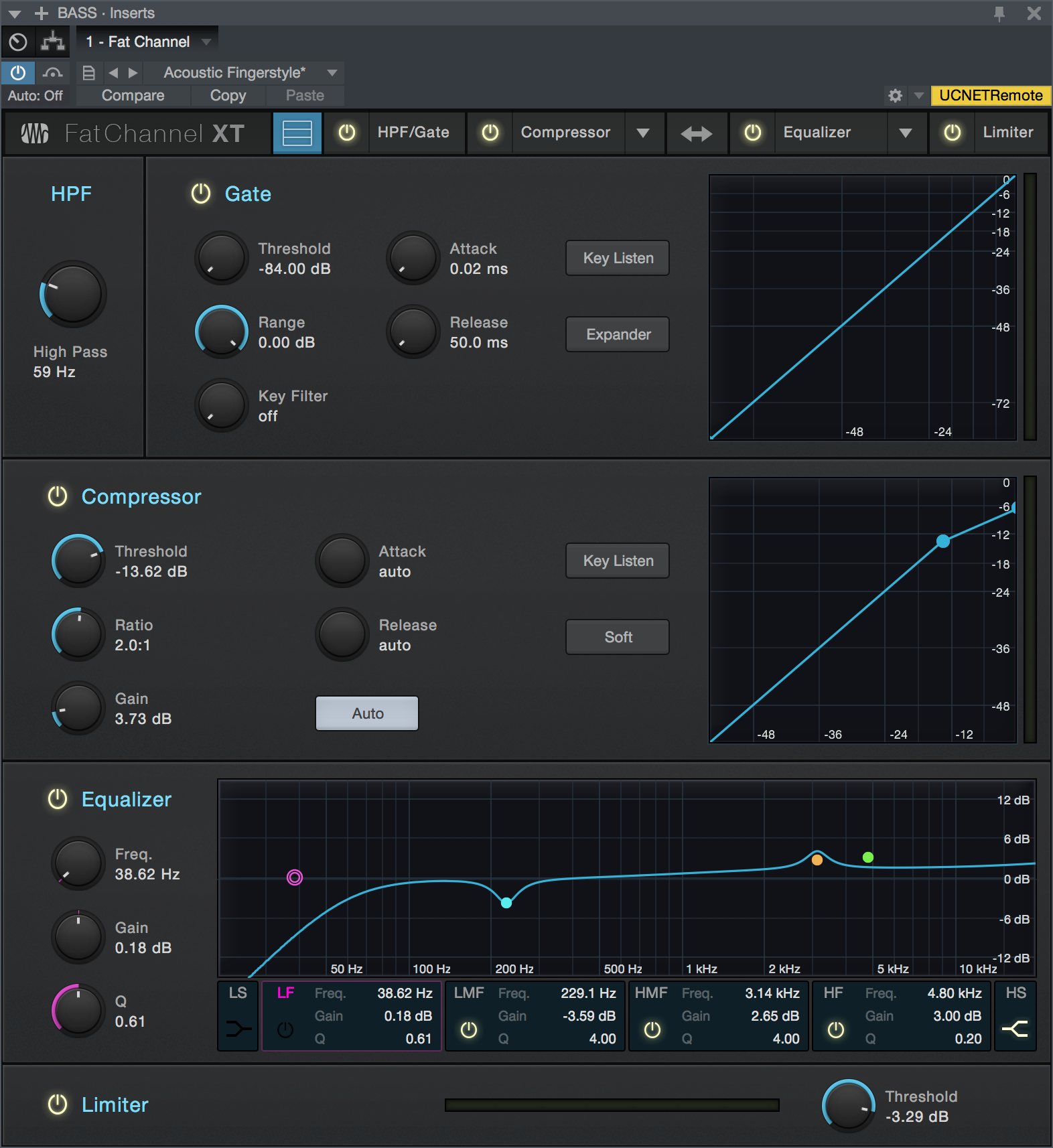
Fat Channel is a complete virtual version of the channel strip found on the PreSonus StudioLive III line of mixers, which allows you to use all Fat Channel XT presets in both Studio One Pro and on StudioLive III. With gate/expander, compressor, parametric EQ and limiter functions, Fat Channel combines many essential processing functions into one easy-to-use tool. Along with its "clean" modern dynamics and EQ processors, Fat Channel XT gives you a selection of high-quality emulations of vintage compressors and EQs to suit your needs.
Fat Channel XT Preset Interchange
To send a Studio One Pro Fat Channel XT preset to StudioLive III or AI, click Export Channel Preset in the Preset Options menu of the Fat Channel XT plug-in header. This saves the current preset to the Universal Control user preset folder, for use by a connected StudioLive III or AI mixer.
Newly added presets from a connected StudioLive III mixer are automatically added to the Studio One Pro Fat Channel XT presets list each time Studio One Pro is launched.
StudioLive AI mixers do not have the ability to use the non-standard EQ and compressor models in Fat Channel XT. If you wish to send a Fat Channel XT preset to your StudioLive AI mixer, be sure to use the standard processor models only.
Fat Channel XT Controls
Fat Channel XT features the following controls:
Header
- Stacked Mode:
 Click this option to toggle the display state of Fat Channel XT. When disabled, only the currently selected processor (such as Gate or Compressor) is displayed. When enabled, all four processors are displayed at once, in a stacked arrangement.
 - Processor Select Buttons (HPF/Gate, Compressor, Equalizer, Limiter): When Fat Channel XT is not in Stacked Mode, click these buttons to display the processor block of your choice.
- Processor Enable/Disable: Click the round button next to the processor name of your choice to toggle the on/off state for that block of processing. Each processor also has its own enable/disable switch within the module interface.
- Compressor and Equalizer Model Selectors: Click the menu next to the name of the Compressor or Equalizer processors to open a Gallery view, from which you can choose the desired Compressor or EQ model. Hover the cursor over each image to view a brief description, then click to select the one you want.
- Compressor offers the following choices:
- Standard: A flexible, modern compressor, with a clean, hi-fi sound.
- Tube: A model of one of the best-loved vintage tube-based opto-compressors. Excels at vocal smoothing and at making bass instruments sound larger-than-life.
- FET: A model of one of the most-used vintage FET-based compressors. Great for adding an aggressive edge and accentuating room sound for drums, guitars, and other highly transient signals.
- Equalizer offers the following choices:
- Standard: A flexible, full-featured modern EQ, with a clean, hi-fi sound.
- Passive: A model of the "rolls-royce" of vintage tube-based passive EQs. Deceptively simple controls and a rich, thick sound make it perfect for gentle tone shaping or adding vintage character.
- Vintage: A model of what some call the "final word" in vintage solid-state EQs. Combines an "everything sounds better through it" quality with musically-chosen EQ frequencies for quick, reliable tonal magic.
- Compressor offers the following choices:
- Swap Comp/EQ Order: Click this button to swap the places of the Compressor and Equalizer processors in the signal chain.
- Sidechain: Engage by clicking the [Sidechain] button at the top of the effect window to allow other sources to control the limiter.
- Sources: Click to display a list of potential sidechain channel sources. A checked box indicates the current source. Multiple selections can be made.
High-Pass Filter (HPF)
- Enable/Disable: Click the "HPF" legend to enable or disable the high-pass filter module.
- High Pass: Sets the frequency of the high-pass filter. Turn all the way left to disengage the filter.
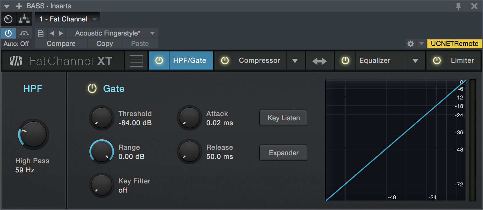
Gate
- Enable/Disable: Click the "Gate" legend to enable or disable the Gate module.
- Threshold: This knob sets the level at which the gate opens. Essentially, all signals above the threshold setting are passed through unaffected, whereas signals below the threshold setting are reduced in level by the amount set by the range control. If the threshold is set all the way to the left, the gate is turned off (always open), allowing all signals to pass through unaffected. You can set the threshold from 0 to -84 dB.
- Range: This adjusts the amount of gain reduction the gate produces. The range can be set from 0 to -84 dB. The Range control is not available when using the expander.
- Key Filter: This knob adjusts the frequency at which the gate opens. Setting a specific frequency, in addition to a specific decibel level, provides more sonic shaping. The key filter can be triggered by the selected channel or bus’s signal or by sidechaining a channel and using its signal as the source.
- Attack (Att): This adjusts the rate at which the gate opens on the selected channel or output. You can set the attack time from 0.02 to 500 ms.
- Release (Rel): Adjusts and displays the rate at which the gate closes on the selected channel. The release time can be set from 0.05 to 2 seconds.
- Key Listen: This button engages and disengages the Key Listen function, which lets you hear how the gate Key Filter is set.
- Expander: Switch the gate into expander mode.
- Interactive Graph: This graph provides a visual representation of the settings and current activity of the gate. You can also adjust the setting by moving the blue dots to adjust Threshold and Range.
Compressor Module - Standard Mode
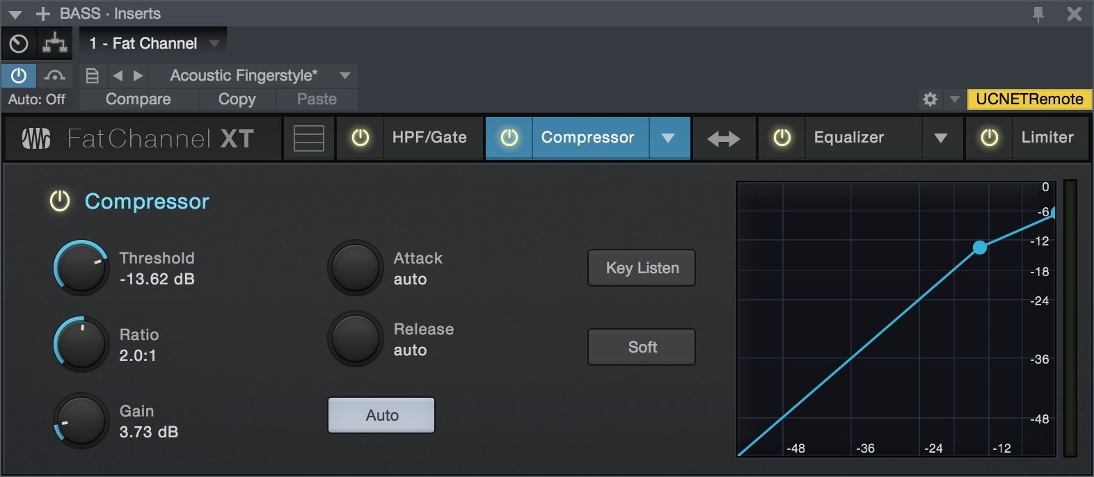
- Enable/Disable: Click the "Compressor" legend to enable or disable the Compressor module.
- Threshold: This knob adjusts the compressor threshold for the selected channel. The compressor engages as soon as the signal level (amplitude) exceeds the threshold value. Moving this control to the left lowers the threshold so that compression begins at a lower amplitude value. The threshold can be set from -56 to 0 dB.
- Ratio: This knob adjusts the compression ratio (or slope). The ratio is a function of the output level versus the input level. For example, if you have the ratio set at 2:1, any signal levels above the threshold setting are compressed at a ratio of 2:1. This means that for every 2 dB of level increase above the threshold, the compressor’s output only increases by 1 dB. The ratio can be set from 1:1 to 18:1 or “limit” which is the equivalent of infinity:1.
- Gain: This sets and displays the makeup gain of the compressor for the selected channel. Compressing a signal usually results in an overall reduction in level (gain reduction), and the Makeup Gain control lets you increase the volume to make up for this gain loss, if desired. You can adjust the Makeup Gain from 0 dB (no gain adjustment) to +28 dB.
- Attack: This adjusts the speed at which the compressor acts on the input signal. A slow attack time (moving the slider to the right) allows the beginning component of a signal (commonly referred to as the initial transient) to pass through, uncompressed, whereas a fast attack time (fully to the left) triggers compression immediately when a signal exceeds the threshold. You can set the attack from 0.2 to 150 milliseconds.
- Release: This determines the length of time the compressor takes to return the gain reduction back to zero (no gain reduction) after crossing below the compression threshold. Release can be set from 2.5 to 900 milliseconds.
- Key Listen: This button engages and disengages the Key Listen function, which lets you listen to the signal that is being fed to the compressor's detector.
- Auto: This enables Automatic Attack and Release mode. When Auto mode is active, the Attack and Release controls become inoperative, and a pre-programmed attack and release curve is used that sets the attack to 10 ms and the release to 150 ms. Meanwhile, all other compressor parameters can still be adjusted manually.
- Soft: This engages soft-knee compression. In normal operating mode, the compressor is set for hard-knee compression, meaning the gain reduction applied to the signal occurs as soon as the input signal level exceeds the threshold value. When the Soft Knee button is engaged, the ratio increases gradually as the signal reaches the threshold.
- Interactive Graph: This graph provides a visual representation of the settings and current activity of the compressor. You can also adjust the setting by moving the blue dot to change the Threshold and Ratio values.
Compressor Module - Tube Mode
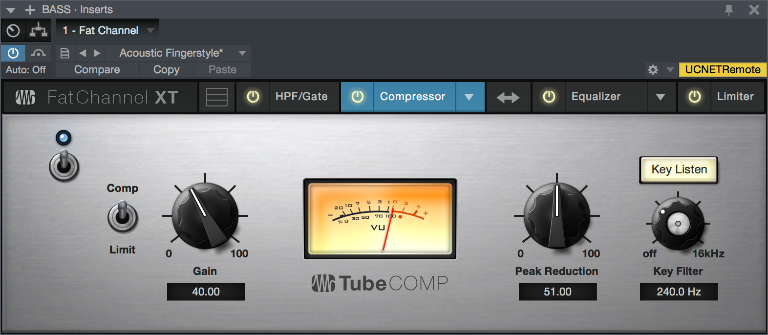
- Enable/Disable: Click the power switch to enable or disable the Tube Compressor module.
- Comp/Limit: Toggles the Tube Compressor between its compressor and limiter modes. When in compressor mode, it acts with a variable ratio of 1:1-10:1. When in limiter mode, it acts with a variable ratio of 10:1-20:1, more aggressively limiting peaks.
- Gain: Sets input gain to the compressor. Because this type of compressor operates in a different way than a standard compressor, much of the way that it affects signals is based on the input level. Try different settings to see what suits your needs.
- Peak Reduction: Sets the amount of peak reduction to apply to the signal. Higher settings result in more gain reduction and more pronounced compression effect.
- Key Filter: Sets the frequency of a high-pass filter that sits in the compressor sidechain. The higher the setting, the more frequencies are excluded from reaching the compressor's detector, with a variety of useful dynamic results. Ranges from "Off" to 16 kHz.
- Key Listen: This button engages and disengages the Key Listen function, which lets you listen to the signal that is being fed to the compressor's detector, after it has passed through the Key Filter.
- VU Meter (Gain Reduction): This vintage-style VU meter shows a smoothed representation of gain reduction applied by the compressor over time.
Compressor Module - FET Mode
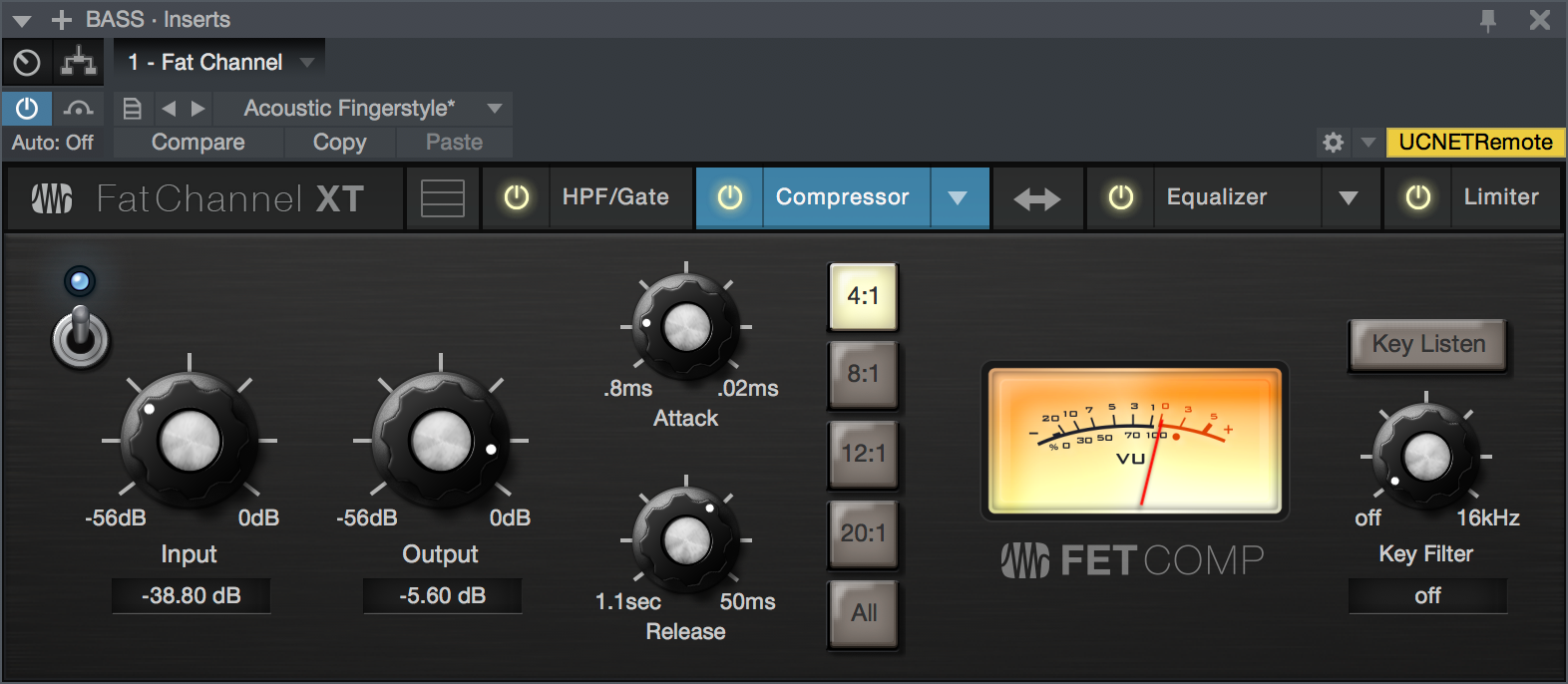
- Enable/Disable: Click the power switch to enable or disable the FET Compressor module.
- Input: Sets input gain to the compressor. This setting affects the action of the compressor, so feel free to try various settings to find the optimal effect for your needs.
- Output: Sets the amount of "makeup gain" to apply to a signal. Once a signal is compressed, its overall level is often reduced. This gain control lets you bring it back up to the proper level after compression occurs.
- Attack: This adjusts the speed at which the compressor acts on the input signal. A slow attack time (moving the slider to the right) allows the beginning component of a signal (commonly referred to as the initial transient) to pass through, uncompressed, whereas a fast attack time (fully to the left) triggers compression immediately when a signal exceeds the threshold. Attack ranges between 0.8 to 0.02 milliseconds.
- Release: This determines the length of time the compressor takes to return the gain reduction back to zero (no gain reduction) after crossing below the compression threshold. Release ranges between 1.1 second to 50milliseconds.
- Ratio Selector Buttons: These buttons let you choose a compression ratio: 4:1, 8:1, 12:1, 20:1, or "All."The ratio is a function of the output level versus the input level. For example, if you have the ratio set at 4:1, any signal levels above the threshold setting are compressed at a ratio of 4:1. This means that for every 4 dB of level increase above the threshold, the compressor’s output only increases by 1 dB. The "All" setting recreates the "all buttons pushed in" setting that helped make this compressor type a legend, providing massive punch and crunch when driven hard.
- Key Filter: Sets the frequency of a high-pass filter that sits in the compressor sidechain. The higher the setting, the more frequencies are excluded from reaching the compressor's detector, with a variety of useful dynamic results. Ranges from "Off" to 16 kHz.
- Key Listen: This button engages and disengages the Key Listen function, which lets you listen to the signal that is being fed to the compressor's detector, after it has passed through the Key Filter.
- VU Meter (Gain Reduction): This vintage-style VU meter shows a smoothed representation of gain reduction applied by the compressor over time.
Equalizer Module - Standard Mode
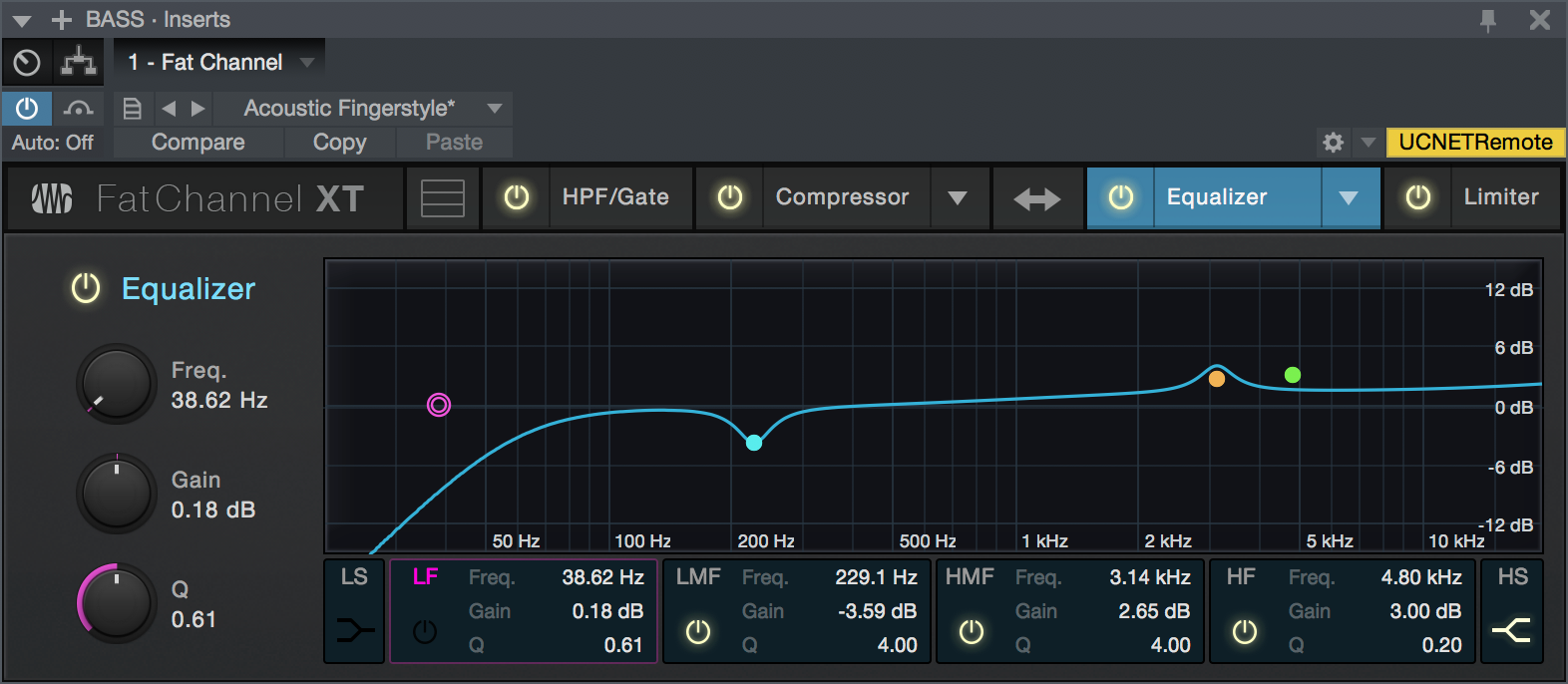
- Enable/Disable: Click this button to enable or disable the Equalizer module.
- Low Shelf (LS) & High Shelf (HS) Buttons: These buttons turns Shelving mode on or off for the High and Low bands. When the Shelf button is engaged, the associated High or Low frequency section is switched from parametric EQ to shelving EQ.
- Band Enable/Disable Buttons: These buttons select which EQ band is being controlled by the Frequency, Gain, and Q controls.
- Freq: This knob selects the center frequency of the corresponding band. You can adjust the center frequency in the following ranges for each band: Low Band: 36 to 465 Hz Low-Mids: 90 Hz to 1.2 kHz Hi-Mids: 380 Hz to 5 kHz Highs: 1.4 to 18 kHz
- Gain: This knob boosts and attenuates the selected frequency with a range of -15 to +15 dB.
- Q: This adjusts the Q value for the corresponding frequency band. The Q is the ratio of the center frequency to the bandwidth. When the center frequency is constant, the bandwidth is inversely proportional to the Q, so as you raise the Q, you narrow the bandwidth. Hence, the smaller the number, the wider the curve.
- Interactive Graph: This graph provides a visual representation of the current settings. You can change the settings by moving the blue dots to adjust the frequency and gain at the same time. The first time you touch a dot, the associated band automatically turns on. Tapping or clicking a dot turns the band on and off.
Equalizer Module - Passive Mode
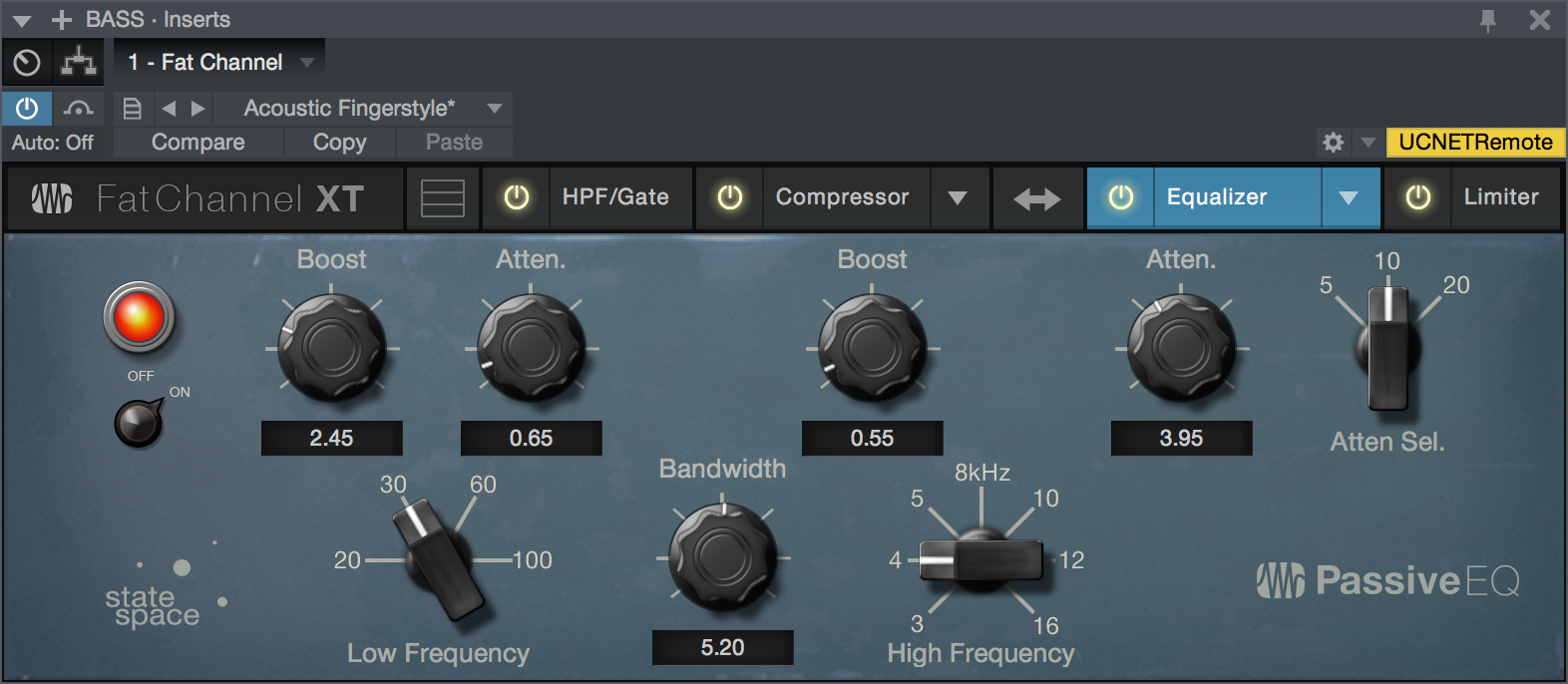
- Enable/Disable: Click this On/Off switch to enable or disable the Passive Equalizer module.
- (Low) Boost: Sets the level of boost applied around the chosen low frequency. This control interacts nicely with the Low Attenuation control, allowing for boosts in apparent bass energy while keeping overall bass energy within optimal limits.
- (Low) Attenuation: Sets the level of attenuation applied around the chosen low frequency. This control interacts nicely with the Low Boost control, allowing for boosts in apparent bass energy while keeping overall bass energy within optimal limits.
- Low Frequency: Sets the center frequency of the band covered by the Low Boost and Low Attenuation controls.
- (Hi-Mid) Boost: Sets the level of boost applied around the chosen high-mid frequency.
- (Hi-Mid) Bandwidth: Sets the Q (or width) of the effect of the high-mid EQ band.
- (Hi-Mid) Frequency: Sets the center frequency of the high-mid EQ band.
- (High) Attenuation: Sets the amount of attenuation applied in a shelving fashion to frequencies at and above the chosen high frequency.
- (High) Attenuation Selector: Sets the frequency at and above which the High Attenuation control attenuates treble content.
Equalizer Module - Vintage Mode
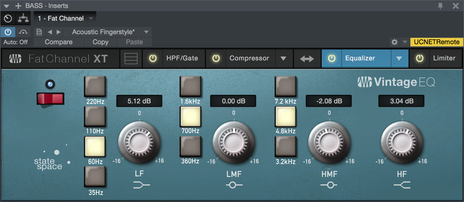
- Enable/Disable: Click the power button to enable or disable the Vintage Equalizer module.
- Low Frequency: Sets the corner frequency of the low-frequency shelving band of this EQ. Choose from 35, 60, 110, or 220 Hz.
- Low Gain (LF): Sets the amount of boost or cut to apply the to low-frequency band of this EQ. Range of plus or minus 16 dB.
- Low-Mid Frequency: Sets the center frequency of the low-mid-frequency band of this EQ. Choose from 360 Hz, 700 Hz, or 1.6 kHz.
- Low-Mid Gain (LMF): Sets the amount of boost or cut to apply to the low-mid-frequency band of this EQ. Range of plus or minus 16 dB.
- High-Mid Frequency: Sets the center frequency of the low-mid-frequency band of this EQ. Choose from 3.2, 4.8, or 7.1 kHz.
- High-Mid Gain (HMF): Sets the amount of boost or cut to apply to the high-mid-frequency band of this EQ. Range of plus or minus 16 dB.
- High Gain (HF): Sets the amount of boost or cut to apply the high-frequency shelving band of this EQ. Range of plus or minus 16 dB.
Limiter Module
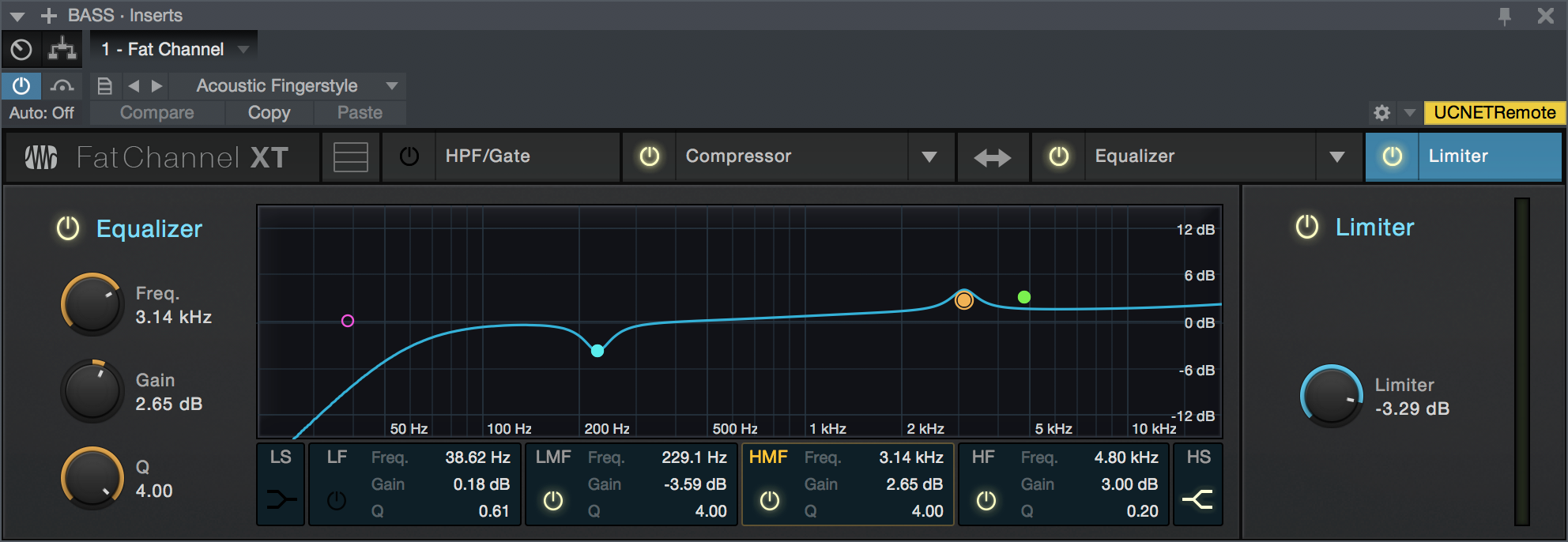
- Enable/Disable: Click the "Limiter" legend to enable or disable the Limiter module.
- Threshold: Sets and displays the threshold of the limiter on the selected channel. The limiter engages as soon as the signal level (amplitude) exceeds the threshold value. Moving this control to the left lowers the threshold so that limiting begins at a lower amplitude value. The threshold can be set from -28 to 0 dB.
Splitter
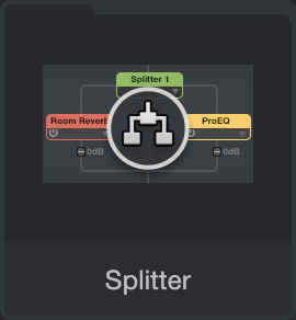
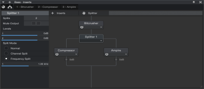
While not technically an effect in itself, Splitter is a special routing module that lets you split signals and process them through multiple parallel effects paths. These split signals are then mixed back into a single signal. You can add an instance of Splitter by dragging and dropping it to a Channel from the Effects section of the Browser, or by clicking-and-dragging from the [Splitter] button to your choice of location in the Channel Editor’s Routing view.
Splitter is enhanced for use with multichannel audio. When using Splitter on a Channel containing a multi-channel Audio Event (like a 5.1 multichannel WAV file), the Channel Split option will provide the appropriate number of splits.
For more on how to use Splitter, see Routing View in the Channel Editor section.