Modulation
Modulation processors are great tools for creating interesting and innovative sounds. Studio One Pro features the following modulation processors:
Autofilter
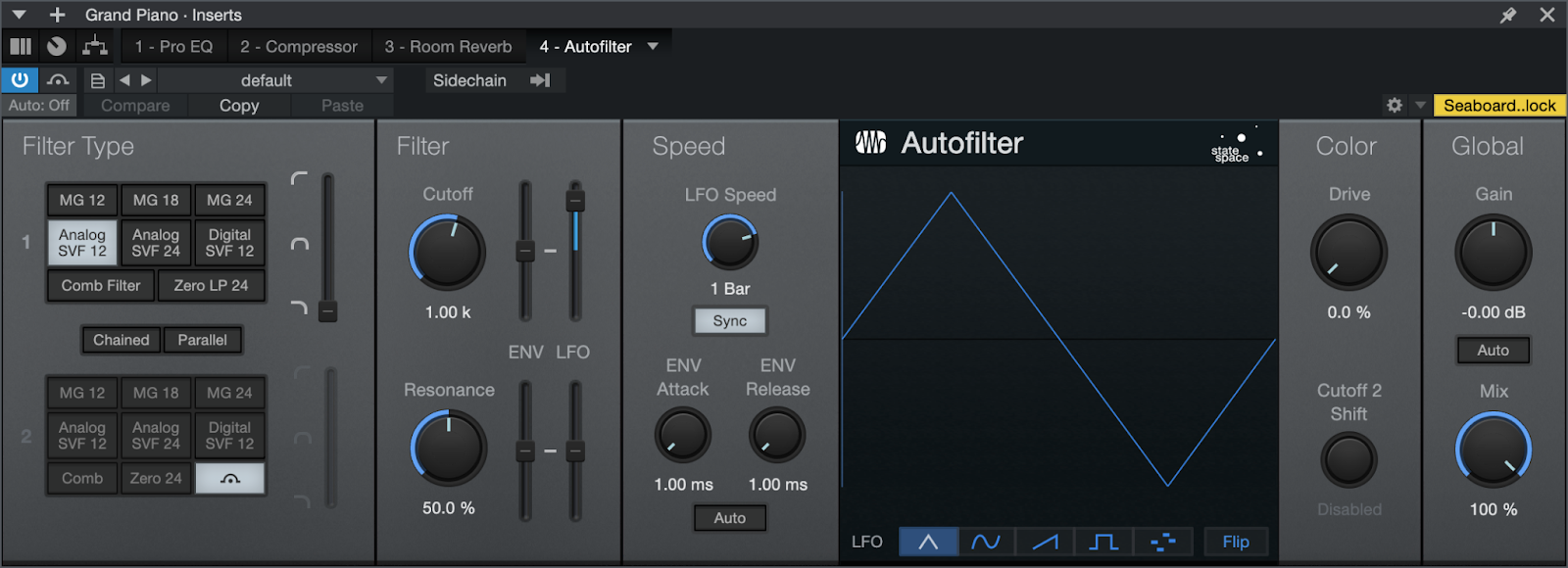
Autofilter features two resonant filters with six selectable filter models. The filter cutoff frequency and resonance can be modulated by an LFO using standard waveforms, a 16-step sequencer, and an envelope. Use Autofilter to create filtered effects from basic filter sweeps to complex tempo-synced rhythmic filter patterns.
The following parameters are available for Autofilter:
- Filter Type:
- Filter 1 and Filter 2: Select from 8 filter emulation types, including Ladder LP 12 dB, 18 dB, and 24 dB; Analog SVF 12 dB and 24 dB, Digital SVF 12 dB, Comb, and Zero Delay LP 24 dB (as found in the Mai Tai and Presence instruments). Note that Filter 2 also has a Bypass option.
- SVFs: State Variable Filters can blend between low-pass, bandpass, and high-pass. Click-drag the vertical Filter Mix fader on the right to blend the filter types.
- Chained/Parallel: Switch the two filters between chained in series (Filter 1 followed by Filter 2; good for adding peaks, creating band-reject filters, etc.) and parallel (Filter 1 and Filter 2 process and output the same signal simultaneously; good for creating wide bandpass filters).
- Filter 1 and Filter 2: Select from 8 filter emulation types, including Ladder LP 12 dB, 18 dB, and 24 dB; Analog SVF 12 dB and 24 dB, Digital SVF 12 dB, Comb, and Zero Delay LP 24 dB (as found in the Mai Tai and Presence instruments). Note that Filter 2 also has a Bypass option.
- Filter:
- Cutoff: Adjusts the cutoff frequency for both filters. Variable from 30 Hz to 16 kHz. Can be modulated by the envelope and LFO.
- Resonance: Adjusts the resonance of the filters. Variable from 0 to 100%.
- ENV/LFO: Adjust the modulation amounts for each filter using the Env and LFO vertical faders. Variable from -100% to 100%. Negative values are phase-inverted. The LFO modulates around the value.
- Speed:
- LFO Speed: Can be synced to tempo or run free.
- Sync: Click to engage/disengage LFO tempo sync. When tempo is synced, the speed is variable from 4/1 to 1/64, with various triplet and dotted-time variants.
- ENV Attack: Adjusts the attack time of the volume envelope, affecting the beginning of cutoff and resonance modulation.
- ENV Release: Adjusts the release time of the volume envelope, affecting the end of cutoff and resonance modulation.
- Auto: Click to engage/disengage automatic envelope-length selection.
- LFO Speed: Can be synced to tempo or run free.
- LFO Steps Display: This area shows the amplitude for each step in the LFO. A vertical line sweeps through the display to indicate the current position in the selected waveform. The LFO runs freely when Sync is disengaged; with Sync engaged, the line starts and stops with Song playback.
- LFO Type: Five LFO types are available along the bottom of the display. Click the buttons to select one of the following types:
- 16 Steps: Click in the LFO display to adjust each step. The steps divide the current Speed/Beats time value. The LFO is bipolar: the value of each step represents amplitude at that step from maximum negative to maximum positive, with the mid-point as the zero-crossing frequency (no modulation). Click-drag to draw unique shapes.
- Waveforms: Select triangle, sine, sawtooth, or square.
- Flip: Inverts the phase of the waveform.
- Color:
- Drive: Adjusts the filter’s feedback overdrive, which features State Space Modeling. Variable from 0 to 100%.
- Cutoff 2 Shift: Adjusts the offset of Filter 2 Cutoff frequency. Variable from -2 octaves to 2 octaves.
- Global:
- Gain: Adjusts Autofilter output gain. Variable from -24 dB to +24 dB.
- Auto: Click to engage Auto-Gain, to keep input and output signals at equivalent levels.
- Mix: Adjusts the mix of the Autofilter-processed signal with the original dry input signal. Variable from 0 to 100%.
- Sidechain: Click the Sidechain button at the top of the effect window to engage sidechain for envelope detection. This allows you to use another Track to control the envelope.
- Sources: Click to display a list of potential sidechain channel sources. A checked box indicates the current source. Multiple selections can be made.
Chorus
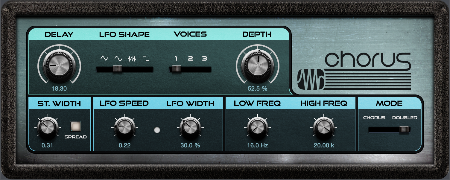
The Chorus is a 1-3-voice chorus processor with optional LFO delay time modulation and stereo width control. Chorus processing is often used on vocal tracks to help create a more full vocal sound so the track fits better in the overall mix. Guitar and synth parts sometimes feature chorus processing for similar reasons.
The following parameters are available for the Chorus:
- Delay: Adjusts the delay of the Chorus voices. The value you set is the delay time between voices.
- LFO Shape: Choose between the four waveforms for the LFO: Triangle, Sine, Sawtooth, or Square.
- Voices: Adjusts the number of added voices in the Chorus; select from 1, 2, or 3.
- LFO: The LFO modulates the Spacing parameter.
- Depth: Adjusts the mix of the processed Chorus output with the dry input signal. Variable from 0 to 100%.
- St. Width: Adjusts the spreading of the Chorus voices in the stereo field. Click the Spread button to engage/disengage the Stereo Width feature.
- LFO Speed: Adjusts the speed of the LFO.
- LFO Width: Adjusts the range of the LFO modulation of Spacing. Variable from 0 to 100%. A value of 100% would modulate the Spacing parameter from 0 to 2x Spacing.
- Low Freq: Sets the corner frequency of the low-cut filter.
- High Freq: Sets the corner frequency of the high-cut filter.
- Mode: Choose between Doubler mode (equivalent to the Chorus effect in Studio One Pro 2.5 and earlier) and Chorus mode, which employs inverse all-pass movement, for truer chorus effect.
Flanger

Flanger creates spatial depths, swirls, timbre shifts, and percussive effects. Flanging is often used on guitar tracks to create interesting shifts in timbre and tone, and it can help create lush synth sounds, as well. It works by splitting an audio signal into two identical signals; applying a varying, short delay to one signal; feeding its output back to its input by varying amounts; and mixing the processed and unprocessed signals. You can modulate Flanger’s delay time with an LFO, which can be tempo-synced.
The following parameters are available for Flanger:
- Feedback: Adjusts the amount of delayed output to be fed back into the input. Variable from -90% to 90%. Negative value results in inverted feedback.
- Delay: Adjusts the delay time for the copied input signal. Variable from 0.25 ms to 10 ms.
- Modulation: This section uses an LFO to modulate the Speed/Beats parameter.
- LFO-Amount: Adjusts the range of the LFO modulation on delay time (speed). Variable from 0 to 100%. A value of 100% would modulate the Speed parameter from 0 to 2x Speed.
- Sync: Click to engage LFO tempo sync. Time is expressed as Beats.
- Speed/Beats: Adjusts the speed of the LFO.
- Speed: Variable from 0.01 Hz to 10 Hz.
- Beats: Select from 4/1 to 1/64 with triplet and dotted-time variants.
- Global:
- Mix: Adjusts the mix of the processed Flanger output with the original dry input signal. Variable from 0 to 100%.
Flanger is enhanced for use with multichannel audio. When assigned to a multi-channel source, the following parameters are added to Flanger:
- Surround Distribution: Changes the modulation offset amount among the output channels.
- Spatial Mode: Choose from Circular, Left/Right, or Front/Rear to affect the dynamic movement of the Flanger effect.
- Stereo Spread: Select the desired amount of stereo width.
Phaser²
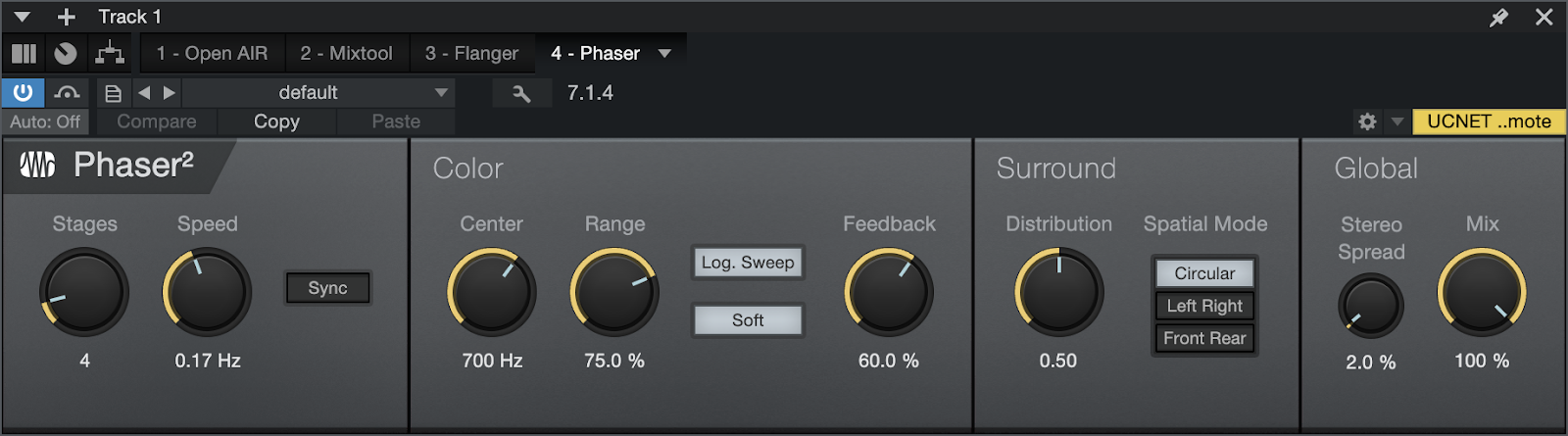
Phaser² applies a variable number of allpass filters in series (one fed into the other), along with one overall feedback loop, to the input signal. Phaser² features an LFO to modulate the center frequencies for each all-pass filter.
The allpass filters function as frequency-dependent delays, so that when the filtered output is added to the original input signal, certain frequencies can be attenuated or amplified as the result of phase shifting. Phasers are commonly used on many types of signals, including synths, guitars, and even vocals, to create a distinctive frequency-shifting effect.
The following parameters are available for Phaser²:
- Stages: Adjusts the number of allpass filter stages in Phaser². Variable from 2 to 20.
- Speed/Beats: Adjusts the speed of the LFO.
- Speed: Variable from 0 Hz to 10 Hz.
- Beats: Select from 4/1 to 1/64, with triplet and dotted-time variants.
- Sync: Click to engage LFO tempo sync. Time is expressed as Beats.
- Color: Modulates the frequency for the allpass filters within the limits set by the Range control, with the Center frequency as the mid-point.
- Center: Adjusts the center frequency for the allpass filters. Variable from 10 Hz to 8 kHz.
- Range: Sets the range of Phaser² modulation from 0 to 100%.
- Log. Sweep: Changes the LFO behavior so that it operates on a logarithmic scale.
- Soft: Selects a triangle wave as the Phaser² modulation shape. When this is disengaged, a sine wave is used as the modulation shape.
- Feedback: Adjusts the amount of the filtered output signal to be fed back into the input. Variable from 0 to 95%.
- Global: Adjusts the speed of the LFO.
- Stereo Spread: Adjusts the spread of each allpass filter in the stereo field from 0 to 100%.
- Mix: Adjusts the blend between the processed Phaser² output and the original dry input signal. Variable from 0 to 100%.
Phaser² is enhanced for use with multichannel audio. When assigned to a multi-channel source, the following parameters are added to Phaser²:
-
Surround Distribution: Changes the modulation offset amount among the output channels.
- Spatial Mode: Choose from Circular, Left/Right, or Front/Rear to affect the dynamic movement of the Phaser effect.
- Stereo Spread: Select the desired amount of stereo width.
Rotor
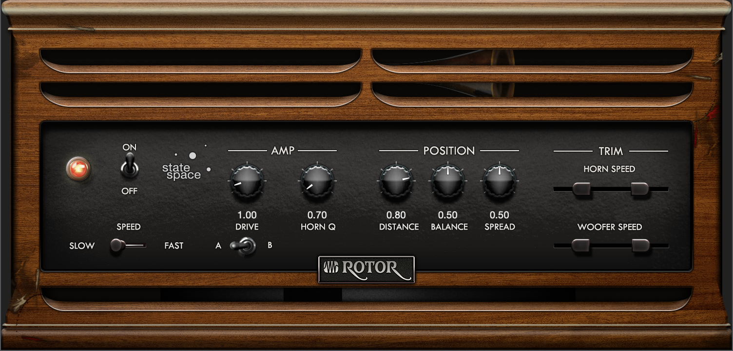
Rotor is a rotary speaker effect that simulates the sound of a tube-powered amplifier with independently rotating high-mid horn and bass woofer, as you might find attached to a classic electric organ. Rotor excels at adding a sense of motion and unique tonal character to organ sounds, guitars, or anything you want to try. Each speaker's rotation can be set to a range of speeds, with realistic braking and acceleration effects when changing speeds.
The following parameters are available for Rotor:
- Off/On: Toggles the rotating action of the virtual speakers on and off, with a smooth speed transition between states.
- Slow/Fast: Toggles between the two preset speeds for the woofer and horn, with a smooth transition between speeds.
- Amp:
- Drive: Add the desired amount of amp drive to the tone using State Space Modeling technology. Lower settings are cleaner, higher settings are more overdriven.
- Horn Q: Blends in a midrange peak that emulates the resonance of rotating horn speakers. Lower settings are more flat, higher settings have a more pronounced resonance.
- A/B: Toggles between two amplifier models that are recreated using State Space Modeling technology.
- Position:
- Distance: Lets you choose the position of the virtual microphone that picks up the rotating speaker. At low settings, the mic is close to the speaker, and the stereo sweeping effects are more pronounced. At higher settings, the mic is further away from the speaker, and the effect is subtler and more diffuse.
- Balance: Lets you blend between the woofer and horn, to achieve the desired tonal balance. Fully down, you mainly hear the woofer. Fully up, you mainly hear the horn.
- Spread: Controls the stereo width of the rotating speaker elements. At low settings, the part of the signal signifying the front of each rotating element moves in a tight, distinct band across the stereo spectrum. At higher settings, the rotating element appears wider and more diffuse.
- Trim:
- Woofer Speed and Horn Speed: These dual-slider controls let you set the speed at which the woofer and horn spin at slow and fast speed settings. You can set them to identical values for more coordinated rotation between woofer and horn, or to differing values that set up contrasting rotations.
Vocoder
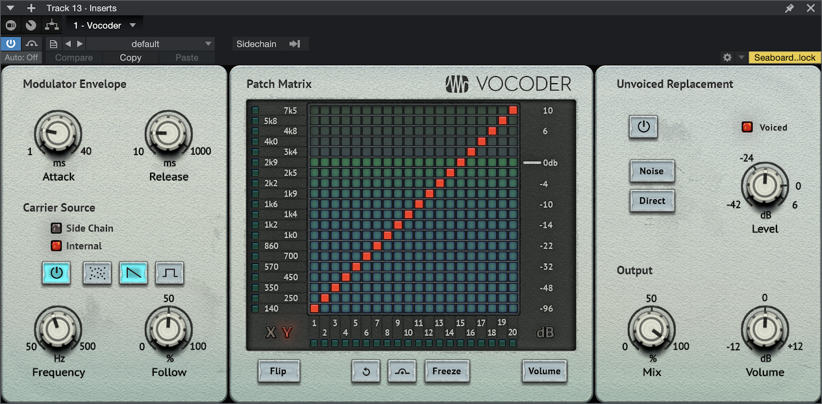
Vocoder is a creative effects processor that combines two input signals to create an entirely new sound. One signal is the modulator, and the other is the carrier.
Vocoder works by splitting the sound of the modulator signal into 20 frequency bands, each with its own bandpass filter and envelope follower. The carrier signal is sent through the filterbank, and the levels adjust to match the frequency of the modulator. The resultant sound is that of the carrier signal being filtered in such a way that its harmonic content resembles that of the modulator signal. When you start manipulating the mapping of frequency band Inputs and Outputs… that's where the real fun starts!
While typically used to give the human voice the texture (and polyphony!) of a synthesized instrument, Vocoder is by no means limited to this application. You’ll find Vocoder to be highly rewarding of experimentation.
Fun fact: hardware vocoders were originally created to encrypt radio transmissions, way back in 1928. They didn’t find use in creative musical applications until the 1970s.
Assigning input sources
Drag and drop Vocoder onto the track you want to process. This Track will serve as Vocoder’s modulator signal.
Using the sidechain menu at the top of the Instrument Editor, assign the second audio source you want. This will be the carrier signal (You can also use an internal source from Vocoder itself as the carrier; more on that below).
We recommend familiarizing yourself with sidechaining by reading the Sidechaining Topic before using Vocoder.
The following parameters are available for Vocoder:
Modulator Envelope
- Attack controls the attack speed of the modulator envelope.
- Release controls the release time of the modulator envelope.
Carrier
Carrier Source: This section is used to set up Vocoder for use with an external (sidechain) carrier signal or an internal carrier signal generated by Vocoder itself. The LEDs will reflect whether a side chain is assigned or not.
- Source select (power button) toggles between sidechain and internal carrier sources. Sidechain must be enabled at the top of the Instrument Inspector for this feature to be available.
The following options apply only when using the Internal carrier.
- Waveform: Select Noise, Saw or Rect waveform. This is for the internal carrier generator only.
- Frequency: Controls the frequency of the internal carrier signal. When the carrier source is set to Noise, Frequency controls a blend between pink noise (left) and white noise (right).
- Follow: Controls modulation amount of the internal carrier pitch as determined by following the input (modulator) level. Essentially an envelope follower that can be used to add some pitch movement to an artificially static voice.
Patch Matrix
The patch matrix is a creative tool which allows you to specify routing from the vocoder’s analyzer section into the synthesizer section. Doing so can help to improve intelligibility of a vocoded voice, or it can be used to push sounds from natural to more unnatural. The possibilities are almost endless!
The outputs of the 20 analyzer bands, identified at the bottom of the matrix, can be patched using “pins” to the inputs of the 20 synthesizer bands, identified on the left of the matrix. The default mapping is a diagonal (1:1).
Routings can be clicked in one at a time, or click and drag to draw a routing configuration quickly.
There are two modes (X and Y) for these routings:
X mode: there is one pin per output band, thus it is possible to assign for example one input band to one or more output bands. Click to activate X mode.
Y mode: there is one pin per input band, thus it is possible to assign or merge multiple input bands into one output band. Click to activate Y mode.
- Flip toggles between X and Y modes (see above).
- Reset resets all pins and volume sliders to the 1:1 (diagonal) configuration.
- Bypass bypasses the patching matrix.
- Freeze: When activated, the contour of the synthesizer bands will be frozen (sample & hold) until the button is disengaged. When you store a preset with Freeze activated, the structure will be stored and reloaded with the preset.
- Volume: Click to toggle the matrix display to show the volume of each of the 20 synthesized output bands. Click or click-and-drag within the matrix to set pins at the desired volume level of each band.
- Analyzer LEDs indicate the level per analyzer band on the left of the matrix.
- Synthesizer LEDs indicate the level per synthesizer band at the bottom of the matrix.
Unvoiced Replacement
Mode: Vocoding of unvoiced speech sounds (f, s, etc.,) is often unsatisfactory. Vocoder offers a function to detect these unvoiced sounds and then replace them with other signals, including noise or a mix of the direct signal.
- Off: No replacement is performed.
- Noise: Unvoiced parts are replaced by a noise signal.
- Direct: A filtered portion of the original carrier signal input is directly mixed into the output.
Speech intelligibility is increased significantly with Noise or Direct mode active.
- Level: Controls the level of the replacement signal.
- Voiced: Indicates whether the input signal is rated as voiced or unvoiced.
Output
- Mix: Wet / Dry mix balance of the carrier input signal and the synthesized output signal.
- Volume: Overall output volume.
X-Trem
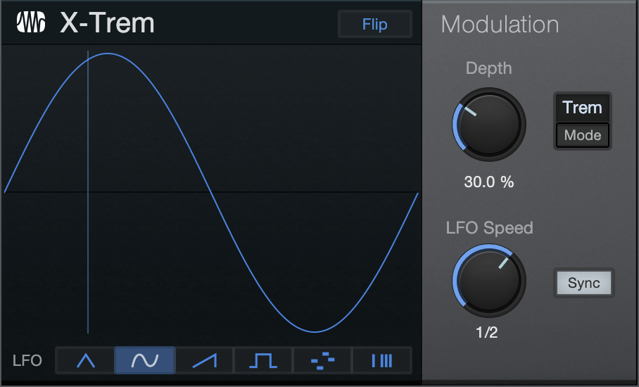
X-Trem is a tremolo effect that applies amplitude modulation at a varying amount and rate over time. The X-Trem features tempo sync and a variable LFO with selectable 16-step and 16-gate sequencers, as well as auto-pan capability. Use X-Trem on any Track to create anything from subtle shifts in amplitude to tempo-synced, glitchy, gated drums; trancy, gated pads; panned hi-hats; and other popular sounds.
The following parameters are available for X-Trem:
- LFO Steps Display: This area shows the amplitude for each step in the LFO. A vertical line sweeps through the display to indicate the current position in the selected waveform. The LFO runs freely when Sync is disengaged; with Sync engaged the line starts and stops with Song playback.
- LFO Type: Six LFO types are available along the bottom of the display. Click the buttons to select one of the following types:
- Waveforms: Select triangle, sine, sawtooth, or square.
- 16 Steps: Click in the LFO display to adjust each step. The steps divide the current Speed/Beats time value; the value of each step represents amplitude/pan at that step from 0/hard left to 100%/hard right. Click-drag to draw unique shapes.
- 16 Gates: Click in the LFO display to open/close the gate at each step. The steps divide the current Speed/Beats time value. For each step, no color fill means the gate is closed, and total color fill means gate is open.
- Flip: This button above the display flips the phase of the selected waveform. It is grayed out and can't be selected when the LFO mode is "16 Steps" or "16 Gates".
- Modulation: This section controls the depth, speed, and destination of the LFO.
- Depth: Adjusts the relative amount of maximum amplitude modulation. Variable from 0 to 100%.
- Pan/Trem: Click to switch the mode of the X-Trem to affect overall amplitude (Trem) or the left- and right-channel balance (Pan). Pan is only selectable on stereo Tracks.
- LFO Speed: Adjusts the speed of the LFO. With Sync disengaged, the speed is expressed in frequency (rate); with Sync engaged, the speed is expressed in rhythmic values (beats).
- Rate: Variable from 0.01 Hz to 30 Hz.
- Beats: Select from 4/1 to 1/64 with triplet and dotted-time variants.
- Sync: Click to engage LFO tempo sync.